Fire hydrants and accessories
Above-ground and underground hydrants in ductile iron and stainless steel, and fully equipped hydrant cabinets – a complete system for supplying water to the intervention.
Fire hydrants
Ductile-iron and stainless-steel body, protected by a fluidised-bed epoxy powder coating. Choose the installation depth (RD) to see the variants and dimensions.

Above-ground hydrant DN80 LC
Non-breakaway type · fluidised-bed epoxy powder coating
Technical data
- Ductile-iron wedge, fully rubber-coated and shaped to the hydrant seat for linear flow
- Automatic air inlet–outlet valve
- Automatic drainage after each use – frost protection
- Head cap to international standards – works with standard hydrant keys
- HAWLE safety couplings on request
Installation depth (RD) and variants
| 2562000 | 2×B |
| 2560000 | 1×B + 2×C |

Above-ground hydrant DN80 / DN100
Non-breakaway type · fluidised-bed epoxy powder coating
Technical data
- Ductile-iron wedge, fully rubber-coated and shaped to the hydrant seat for linear flow
- Automatic air inlet–outlet valve
- Automatic drainage after each use – frost protection
- Head cap to international standards – works with standard hydrant keys
- HAWLE safety couplings on request
Installation depth (RD) and variants
| 2500001 | DN80 · 1×B + 2×C |
| 2504001 | DN80 · 1×A + 2×B |
| 2500301 | DN100 · 2×B |
| 2501110 | DN100 · 2×B |
| 2500003 | DN100 · 1×B + 2×C |
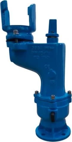
Underground hydrant DN50
With claw coupling · fluidised-bed epoxy powder coating
Technical data
- Ductile-iron wedge, fully rubber-coated, for linear flow
- Automatic drainage after each use
- Claw coupling to national standards – for standard underground hydrant standpipes (e.g. B/2C in the KHNZ-2 cabinet)
Installation depth (RD) and variants
| 2502901 | DN50 · claw coupling |
Hydrant cabinets
Metal cabinets with hoses, branch pipes and keys – ready to connect to the hydrant or to mount on a wall.
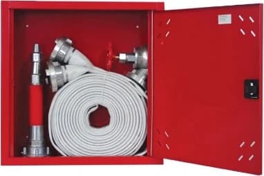
Wall-mounted fire hydrant cabinet
For indoor hydrants in buildings: a single-door metal cabinet mounted on the wall, with the hose and branch pipe ready for first response.
- Dimensions
- 500 × 500 × 140 mm
- Doors
- 1
- Mounting
- On the wall
- Hoses
- 1 × 15 m
Equipment included
- 1
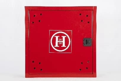 Single-door metal hydrant cabinet500 × 500 × 140 mm
- 1
 Fire hose with Storz couplingsØ52 mm (C), 15 m long
- 1Fire branch pipe Ø52 mm (C)In two versions, to choose from:
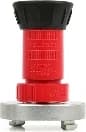 With rotary valve Ø52 mmor
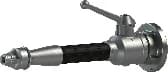 With ball valve, aluminium
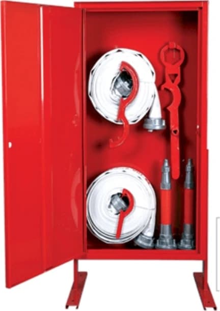
Above-ground fire hydrant cabinet
Placed next to the above-ground hydrant, on legs: a tall single-door cabinet with hoses, branch pipes and keys for a quick connection to the hydrant.
- Dimensions
- 540 × 1080 × 290 mm
- Doors
- 1
- Mounting
- On legs, next to the hydrant
- Hoses
- 2 × 15 m (room for up to 4)
Equipment included
- 1Single-door metal hydrant cabinet540 × 1080 × 290 mm
- 2Fire hoses with Storz couplingsØ52 mm (C), 15 m – room for up to 4 hoses
- 2Fire branch pipe with ball valveØ52 mm (C)
- 1
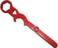 Above-ground hydrant key
- 1
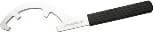 ABC coupling spanner
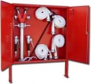
Underground fire hydrant cabinet
For underground hydrants: a wide double-door cabinet with the B/2C hydrant standpipe, four hoses and the T-key for opening the hydrant.
- Dimensions
- 1080 × 1080/1060 × 185 mm
- Doors
- 2
- Mounting
- On legs
- Hoses
- 4 × 15 m
Equipment included
- 1Double-door metal hydrant cabinet1080 × 1080/1060 × 185 mm
- 1
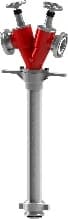 Underground hydrant standpipe B/2CB inlet, two C outlets
- 4
 Fire hoses with Storz couplingsØ52 mm (C), 15 m
- 2Fire branch pipe with ball valveØ52 mm (C)
- 1
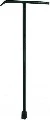 Underground hydrant T-key
- 1ABC coupling spanner
How they combine
+The cabinet stands next to the above-ground hydrant; the C hoses connect directly to the hydrant's Storz outlets.
+The B/2C standpipe from the cabinet is fitted to the underground hydrant and gives two C outlets.
The wall cabinet connects to the valve of the building's indoor hydrant network.
Hydrant comparison
| DN80 LCAbove-ground hydrant DN80 LC | DN80 / DN100Above-ground hydrant DN80 / DN100 | DN50Underground hydrant DN50 | |
|---|---|---|---|
| Type | Above-ground | Above-ground | Underground |
| DN | 80 | 80 / 100 | 50 |
| Nominal pressure | PN 10/16 | PN 10/16 | PN 10 |
| Depth RD (mm) | 750 · 1000 · 1250 · 1500 | 1000 · 1250 · 1500 | 750 · 1000 · 1250 · 1500 |
| Height H (mm) | 1575 · 1825 · 2075 · 2325 | 2000 · 2250 · 2500 | 540 · 790 · 1045 · 1295 |
| Weight (kg) | 31 · 33 · 36 · 38 | 48 / 49 · 51 / 52 · 53 / 54 (DN80 / DN100) | 24 · 29 · 34 · 39 |
| Outlets | 2 × B · 1 × B + 2 × C | 1 × B + 2 × C · 1 × A + 2 × B · 2 × B | Claw coupling |
Cabinet comparison
| KH-1Wall-mounted fire hydrant cabinet | KHMZ-1Above-ground fire hydrant cabinet | KHNZ-2Underground fire hydrant cabinet | |
|---|---|---|---|
| Use | Indoor wall hydrant | Next to the above-ground hydrant | For the underground hydrant |
| Dimensions (mm) | 500 × 500 × 140 | 540 × 1080 × 290 | 1080 × 1080/1060 × 185 |
| Doors | 1 | 1 | 2 |
| Mounting | On the wall | On legs, next to the hydrant | On legs |
| Hoses Ø52 mm (C), 15 m | 1 × 15 m | 2 × 15 m (room for up to 4) | 4 × 15 m |
| Branch pipes Ø52 mm with ball valve | 1 (rotary or ball valve) | 2 | 2 |
| Keys | – | Above-ground hydrant key · ABC coupling spanner | Underground hydrant T-key · ABC coupling spanner |
| Hydrant standpipe | – | – | B/2C |
From supply to maintenance
Cabinets are supplied fully equipped and installed next to the hydrant or on the wall, according to the fire-protection design.
Pressure testing and flow measurement of the network, under authorisation AME–MPB no. 167/02.
Periodic checks of hoses, branch pipes, couplings and the cabinet, following the hydrant inspection protocol.
Need a quote for hydrants, cabinets or a whole hydrant network?
Request a quote